Safety Relief Valves
The primary function of a safety valve is to protect property and life.
Because
a safety valve is often the last device to prevent catastrophic failure
under pressure conditions, it is important that the valve works at all
times i.e. it must be 100% reliable.
Safety valves should be
installed wherever the maximum allowable working pressure of a system or
pressure containing vessel is likely to be exceeded, in particular
under fault conditions due to the failure of another piece of equipment
in the system.
Pressure excess can be generated in a number of different ways including:
- Failure of a cooling system allowing vapour or fluid to expand
- Compressed air or electrical power failure to control instrumentation
- Plant fires
- During the start-up conditions of a plant
The term “Safety Valve” and “Relief Valve”
are generic terms to describe a variety of pressure relief devices. A
wide range is available based on the application and required
performance criteria. The different designs are required to meet
numerous national standards.
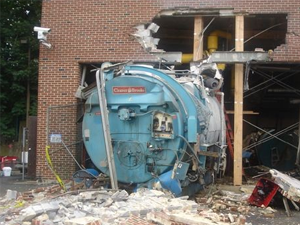
The images below show the devastating results of a failed Safety
valve (due to poor maintenace) or ones which have been incorrectly
sized, installed or maintained.
 |
 |
 |
| Air Receiver Explosion |
High School Boiler |
Industrial Boiler Explosion |
 |
 |
 |
| Implosion of a Rail Tanker (failed Vac Valve) |
Explosion at an Oil Refinery |
BP Deep Water Horizon Explosion |
Definitions
ASME / ANSI PTC 25.3 standards (USA)
Pressure relief valve – (This is a general term, which includes safety valves, relief valves and safety relief valves.)
A
spring-loaded pressure relief valve which is designed to open to
relieve excess pressure and to reclose and prevent the further flow of
fluid after normal conditions have been restored. It is characterised by
a rapid-opening 'pop' action or by opening in a manner generally
proportional to the increase in pressure over the opening pressure. It
may be used for either compressible or incompressible fluids, depending
on design, adjustment, or application.
Safety valve - A pressure relief valve actuated by inlet static pressure and characterised by rapid opening or pop action.
Relief valve
- A pressure relief device actuated by inlet static pressure having a
gradual lift generally proportional to the increase in pressure over
opening pressure.
Safety relief valve - A pressure
relief valve characterised by rapid opening or pop action, or by opening
in proportion to the increase in pressure over the opening pressure,
depending on the application, and which may be used either for liquid or
compressible fluid.
European standard EN ISO 4126-1
Safety valve - A valve which automatically, without
the assistance of any energy other than that of the fluid concerned,
discharges a quantity of the fluid so as to prevent a predetermined safe
pressure being exceeded, and which is designed to re-close and prevent
further flow of fluid after normal pressure conditions of service have
been restored.
A Standard Valve
The images below show a standard Relief valve and a standard Safety valve from a well-known UK manufacturer.
Each manufacturer does things slightly differently however all of the
basic components and principles of operation are the same. As described
previously, a safety valve differs from a relief valve in that it opens
rapidly once the set pressure has been reached. For the same inlet size
and with the valve in the closed position, the surface area that the
pressure on the inlet side will see is the same. When the set pressure
is reached and the valve starts to open, the disk on a Safety valve is
larger (see the diagrams below) and hence the same pressure then sees a
much larger surface area and consequently the force increases greatly
causing the valve to open quickly and hence the characteristic pop
action.

Figure 1 - Lifting lever (3), Spring (4), Spindle (17), Bonnet (6), Inlet body (12), Disk (9), Spring Carrier (16)
The image below shows the above Safety valves and Relief valves
dismantled. The disk diameter on the 1" (DN25) Safety valve is only 7mm
larger than on the Relief valve which doesnt sound like much, but when
you calculate the areas it is an increase of 36%.

A dismantled 1" (DN25) Safety Valve and a dismantled 1" (DN25) Relief Valve from the same Manufacturer
Basic Safety Valve Principles
This diagram represents a Safety valve in its very simplest form. The
force acting on the inlet side of the disk is acting against the force
applied by the spring plus the force applied by the back pressure on the
top of the disk.
Figure 2 - Simple Valve Model
The valve remains closed when(PI x Ab) < Fs + (PB x At), is in
equilibrium when(PI x Ab) = Fs + (PB x At) and opens when(PI x Ab) >
Fs + (PB x At) were PI = Inlet pressure, PB = Back pressure, At = Top of
disk area, Ab = Bottom of disk area. Things to notice from this design
are that if PB is variable and quite large relative to PI, then this
will cause the pressure at which the valve opens to vary which is
undesirable. The following two designs (Fig 3 & Fig 4) are available
that eliminate the effect of back pressure on the set pressure.
Figure 3 - Fitted with belows
Figure 4 - Piston design
The bellows prevents backpressure acting on the top side of the disk. In
relation to the piston there is no top side within the main body of the
valve hence again the back pressure cannot affect the set pressure.
Bellows failure is an important concern in critical applications where a
very precise set pressure is required. In these cases some mechanism to
detect a leak of process medium out of the top vent would be
implemented. Piston designs are not usually found in conventional Safety
valves but are more common in Pilot Operated Safety valves.
Guidance on when to use Bellows
API 520 Practice Guidelines: a conventional design should not typically
be used when the built-up backpressure is greater than 10% of the set
pressure at 10% over pressure. European standard EN ISO 4126: the
built-up backpressure should be limited to 10% of the set pressure when
the valve is discharging at the certified capacity.
Other Backpressure concerns
A large PB will also affect the flowrate of the valve when open.
The total backpressure is generated from two components, superimposed backpressure and the built-up backpressure
- Superimposed back pressure: the static pressure that exists on the outlet side of a closed valve.
- Built-up back pressure: the additional pressure generated on the outlet side when the valve is discharging.
In a conventional design (no bellows), the superimposed backpressure
will affect the opening characteristic and set value, but the combined
backpressure will alter the closing (blowdown) and re-seat value.
Performance Summary
Overpressure is the percentage over the set pressure by which the
valve is fully open. The blowdown is the percentage below the set
pressure by which the valve is fully closed.
Figure 5 – Relationship between pressure and lift for a typical safety valve
Table 1 – Safety Valve Performance Summary
Table 2 – Safety Valve Standards
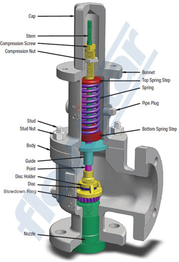
Components of an API Safety Valve
Please note depending upon the manufacturer they may differ slightly to that shown below.
Figure 6 – Typical Safety Valve Components
The basic elements of the design are right angle pattern valve body,
inlet can be either a full nozzle or a semi-nozzle type. With a full
nozzle design has the “wetted” inlet tract formed from one piece (as per
figure 6) with the seat integrated into the top of the nozzle. The
internal bore of the nozzle and the disc is the only part of the valve
that is exposed to the process fluid with the valve in the closed
position. A semi-nozzle design consists of a seating ring fitted into
the body.The disc is held onto the seat by the stem, with the downward
force coming from the compression on the spring mounted in the bonnet.
The amount of compression on the spring is adjusted by the spring
adjuster under the cap.
Bonnet Types
Figure 7 - Open Bonnet
Figure 8 - Closed Bonnet
Unless bellows or diaphragm sealing is used, process fluid will enter
the spring housing (or bonnet). The amount of fluid depends on the
particular design of safety valve. If emission of this fluid into the
atmosphere is acceptable, the spring housing may be vented to the
atmosphere - an open bonnet. This is usually advantageous when the
safety valve is used on high temperature fluids or for boiler
applications as, otherwise, high temperatures can relax the spring,
altering the set pressure of the valve. However, using an open bonnet
exposes the valve spring and internals to environmental conditions,
which can lead to damage and corrosion of the spring.
When the fluid
must be completely contained by the safety valve (and the discharge
system), it is necessary to use a closed bonnet, which is not vented to
the atmosphere. This type of spring enclosure is almost universally used
for small screwed valves and, it is becoming increasingly common on
many valve ranges since, particularly on steam, discharge of the fluid
could be hazardous to personnel.
Typical Cap Options
Open Lifting Lever
Figure 9 - With a Lifting Lever Fitted
A lifting mechanism is recommended to test for correct valve
operation at all times where corrosion, caking, or any deposit could
prevent the opening operation.
Foreign particles can lodge under the
seat of the valve when it discharges. The lifting lever allows you to
lift the valve and flush the obstruction. Pressure relief valves for
Section VIII require a lift lever on all air, steam, and hot water
valves used at temperatures over 60 degC. Typically used where periodic
testing of the valve in location is desired to assure its operation.
With an Open lifting lever design, when the valve discharges, fluid
media will escape into the atmosphere around the open lifting lever
assembly. If this is not desirable or when back pressure is present you
would select a Packed Lifting Lever design.
Packed Lifting Lever
Figure 10 - Packed Lifting Lever
As described above, this type is selected where leakage of the media
to the atmosphere during valve discharge or during back pressure would
be un-desirable. A packed lever design is a completely sealed assembly.
Bolted Cap
Figure 11 - Bolted Cap
Some people consider a bolted and gasketed design better to the
standard screw cap for applications with back pressure and / or
vibration hence some manufacturers offer this as an option.
Gag Screw / Test Gag
Figure 12 - Gag Screw / Test Gag
Under certain circumstances i.e. under the start-up conditions of a
plant or to pressure test the system in a controlled environment, it may
be required that the valve is prevented from opening.This is achieved
by screwing the bolt (shown on the wire) into the cap which screws down
onto the stem and prevents it lifting. Obviously it is important that
test gags are removed prior to placing the valve into service.
Other Typical Options Available
Balanced Bellows
Figure 13 - Balanced Bellows
The bellows is designed to cover the same area on the back of the
disc equal to the seat area hence the back pressure will have no effect
on the set pressure. See the previous section “Basic Safety Valve
Principles”. Bellows also protects the spindle, spindle guide and spring
from the process medium.
Operation Indicator
Figure 14 - Operation Indicator
A micro switch is fitted on the exterior of the valve which is activated when the stem rises in the valve.
Steam Jackets
A bolt on steam jacket for preserving the valve body temperature.
Typically used on fluids to prevent solidification of the flowing
viscous fluids.
Safety Valve Operation
A disc is held against the nozzle by a spring, which is contained in a
cast bonnet. The spring is adjusted by a compression screw to permit
the calibration of opening or set pressure. An adjustable nozzle ring,
threaded onto the nozzle, controls the geometry of the fluid exit
control chamber (also known as a huddling chamber). The control chamber
(huddling chamber) geometry is very important in controlling valve
opening and closing pressures and stability of operation. The nozzle
ring is locked into position by a ring pin assembly as shown in Figure
15 below.
Figure 15
Figure 16 - Relationship of Nozzle Area to Control Chamber (Huddling Chamber)
Under normal system operation the valve remains in the closed position
because the spring force (Fs) is greater than the system pressure acting
on the internal nozzle seating area (PA). If system pressure increases
to a point when these forces are equal, then the set pressure is
reached. The disc lifts and fluid flows through the valve. When pressure
in the system returns to a safe level, the valve closes.
Just prior
to reaching set point, the pressure relief valve leaks system fluid
into the huddling chamber. The fluid now acts on a larger area of the
disc inside the huddling chamber (PAh), causing the valve to experience
an instantaneous increase in the opening force. Refer to the figure 16
above to see relationship between Nozzle Area (A) and the Huddling
Chamber Area (Ah). System pressure acting on the larger area will
suddenly open the safety relief valve at a rapid rate.
Although the
opening is rapid and dramatic, the valve does not open fully at set
point. The system pressure must increase above set point to open the
valve to its full lift and capacity position. Maximum lift and certified
flow rates will be achieved within the allowable limits (overpressure)
established by various codes and standards. All pressure relief ales are
allowed an overpressure allowance to reach full rated flow. The
allowable over pressure can vary from 10% to 21% on unfired vessels and
systems, depending on the sizing basis, number of valves, and whether a
fire condition is encountered.
Once the valve has controlled the
pressure excursion, system pressure will start to reduce. Since the
huddling chamber area is now controlling the exit fluid flow, system
pressure must reduce below the set point before the spring force is able
to close the valve. The difference between the set pressure and the
closing pressure is called blowdown, and is usually expressed as a
percentage of set pressure. The typical blowdown can vary from 7% to
10%, the industry standard.
The nozzle ring adjustment changes the
shape and volume of the huddling chamber, and its position will affect
both the opening and the closing characteristics of the valve. When the
nozzle ring is adjusted to its top position, the huddling chamber is
restricted to its maximum. The valve will usually pop very distinctly
with a minimum simmer (leakage before opening), but the blowdown will
increase. When the nozzle ring is lowered to its lowest position,
minimal restriction to the huddling chamber occurs. At this position,
simmer increases and the blowdown decreases. The final ring position is
somewhere between these two extremes to provide optimal performance.
Liquid Service Operation
On liquid service, a different dynamic situation exists. Liquids do not
expand when flowing across orifices, and a small amount of fluid flow
across the nozzle will produces a large local pressure drop at the
nozzle orifice. This local pressure drop causes the spring to reclose
the valve if the fluid flow is minimal. Liquids leaking into the
huddling chamber can quickly drain out by gravity and prevent fluid
pressure from building up in the secondary area of the huddling chamber.
Liquid relief valves are thus susceptible to a phenomenon called
chatter, especially at low fluid flow rates. Chatter is the rapid
opening and closing of the pressure relief valve and is always
destructive.
Because of the difference in the characteristics of
gases and liquids, some valve designs require a special liquid trim in
order to meet ASME Code Section VIII performance criteria of full rated
liquid flow at 10% overpressure. With liquids since no visible or
audible pop is heard at set point, the set pressure is defined as the
pressure when the first heavy flow occurs (a pencil sized steady stream
of water that remains unbroken for approximately one inch).
Testing / Maintenance of Safety Valves
Manufacturers usually state their recommended testing procedure and
testing intervals in their Installation, Operating and Maintenance
Instructions (IOM). Typically, they recommend a manual test every 3 or 6
months (assuming it has a lifting lever) and a set pressure test every
12 months. It is sensible to incorporate these into your maintenance
plan so they are not missed. Sometimes your insurance company may
require them to be tested even more regularly than this i.e. every 6
months. Testing in most cases involves removing them from your system
and having them recertified in an approved workshop.
- If you have a system that is shut down for annual maintenance then
this is an ideal time to remove your Safety valves and have them
inspected and recertified.
- For systems that can only be off for short periods of time, it is
sensible to keep a spare valve to swap over and then the removed valve
can be inspected and recertified.
- For systems that cannot be shut down, you will need to use a
changeover valve which allows you to swap between Safety valves allowing
one to be removed for inspection and testing.
- For larger Safety valves on systems that run continuously, you may
consider using in-situ testing. This method does have some limitations
however since you cannot visually inspect the inside of the valve, but
it will tell you if the valve is opening at the correct set pressure.
Common Faults with Safety Valves
Safety valves and Relief valves are extremely reliable. The most common issues we come across however are:
(a) A valve passing (leaking) on the outlet side when the valve is
supposed to be closed. This can happen to valves of any age (new or old)
and occurs if debris contained in the medium passes through the valve
at a point when the valve lifts, and the debris either traps or damages
the internals of the valve. On soft seated valves, hard particles may
embed themselves in the soft material causing re-sealing issues. If your
valve has a lifting lever and it is safe to do so, then it is worth
lifting the handle for a few seconds which will hopefully clear any
debris allowing the valve to reseal correctly. If this isn’t an option
or it doesn’t cure the problem, then the valve will need to be removed
and returned for maintenance and recertification. The time we often see
this the most is during the startup of a system and there is a pressure
spike, hence this is why it is extremely important that a system is
flushed out well before hand.
(b) Corrosion / wear which is usually only a problem on older valves or those in extremely harsh environments.