Sarasin
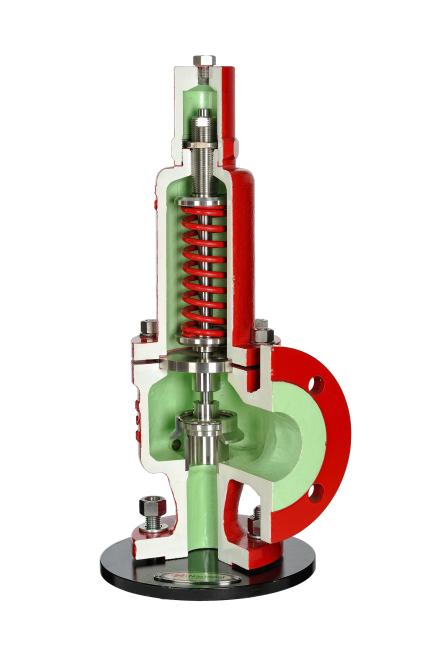
steam safety valve / for boilers / high-pressure / flange - Sarasin-RSBD™ Starsteam™ V


steam safety valve / for boilers / high-pressure / flange - Sarasin-RSBD™ Starsteam™ V


توضیحات و شرح خدمات اورهال
ما خدمات جامع برای تست، و تعمیر شیرهای ایمنی
ارائه می دهیم. خدمات ما حرفه ای، سریع و کارآمد است و توسط تیم مهندسی وکارکنان آموزش دیده انجام می شود.
بازسازی استاندارد
پیش آزمون (تست اولیه)
دمونتاژ (پیاده کردن)
بازرسی
تمیز کردن داخلی و خارجی
لایه برداری سطحی (در صورت لزوم)
لپینگ دیسک و تازل
تست و تنظیم مجدد
تأیید مجدد
مهر و موم و برچسب (در صورت لزوم)
اگر به هر گونه کمک نیاز دارید، لطفا با ما تماس بگیرید
Safety and Relief Valves are completely governed by codes and regulations. The two major codes are ASME (USA) and PED (Europe), and both are laws and failure to comply is a criminal offence. As you would imagine, they are both very similar but also do have some distinct differences. Because the codes are law, they must be adhered to when equipment is installed in a specific region. Most manufacturers therefore have both approvals. When installing a safety valve however, to be compliant with these codes you not only need to use an approved supplier, but you also need to select settings, and install them in accordance with the codes.
The governing standards and recommended practises are API 520 (USA) and EN4126 (Europe). API 520 incorporates more detail on correction factors (more conservative) for back pressure and viscosity, hence is the most widely used for valve sizing.
Some Others
The European PED, from a legal perspective replaces the very many local codes in all European member states such as BS (UK), TUV (Germany), AFNOR NFE (France), Stoomwezen (The Netherlands), ISPESL (Italy).
Some European users may also stipulate their local code however in addition to the PED. Local codes have different ways of presenting things but often the results are the same.
Compliance with the PED allows a manufacturer to CE mark their product.
ASME B16.34 - Applies to valves with flanged, threaded, and welding ends: This standard covers pressure/temperature ratings, dimensions, tolerances, materials, non-destructive examination requirements, testing and marking. This standard is not specifically applicable to Safety Relief Valves but is often used by manufacturers as good engineering practice.
ASME B16.5 - Applies to pipe flanges and flange fittings: Provides allowable materials, pressure / temperature limits and flange dimensions for standard ANSI flanges.

The term “Safety Valve” and “Relief Valve” are generic terms to describe a variety of pressure relief devices. A wide range is available based on the application and required performance criteria. The different designs are required to meet numerous national standards.
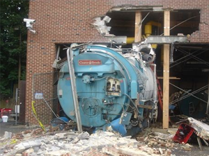
The images below show the devastating results of a failed Safety valve (due to poor maintenace) or ones which have been incorrectly sized, installed or maintained.
 |
 |
 |
| Air Receiver Explosion | High School Boiler | Industrial Boiler Explosion |
 |
 |
 |
| Implosion of a Rail Tanker (failed Vac Valve) | Explosion at an Oil Refinery | BP Deep Water Horizon Explosion |
Safety valve - A valve which automatically, without the assistance of any energy other than that of the fluid concerned, discharges a quantity of the fluid so as to prevent a predetermined safe pressure being exceeded, and which is designed to re-close and prevent further flow of fluid after normal pressure conditions of service have been restored.
The images below show a standard Relief valve and a standard Safety valve from a well-known UK manufacturer. Each manufacturer does things slightly differently however all of the basic components and principles of operation are the same. As described previously, a safety valve differs from a relief valve in that it opens rapidly once the set pressure has been reached. For the same inlet size and with the valve in the closed position, the surface area that the pressure on the inlet side will see is the same. When the set pressure is reached and the valve starts to open, the disk on a Safety valve is larger (see the diagrams below) and hence the same pressure then sees a much larger surface area and consequently the force increases greatly causing the valve to open quickly and hence the characteristic pop action.

The image below shows the above Safety valves and Relief valves dismantled. The disk diameter on the 1" (DN25) Safety valve is only 7mm larger than on the Relief valve which doesnt sound like much, but when you calculate the areas it is an increase of 36%.

This diagram represents a Safety valve in its very simplest form. The force acting on the inlet side of the disk is acting against the force applied by the spring plus the force applied by the back pressure on the top of the disk.


In a conventional design (no bellows), the superimposed backpressure will affect the opening characteristic and set value, but the combined backpressure will alter the closing (blowdown) and re-seat value.
Overpressure is the percentage over the set pressure by which the valve is fully open. The blowdown is the percentage below the set pressure by which the valve is fully closed.


Please note depending upon the manufacturer they may differ slightly to that shown below.

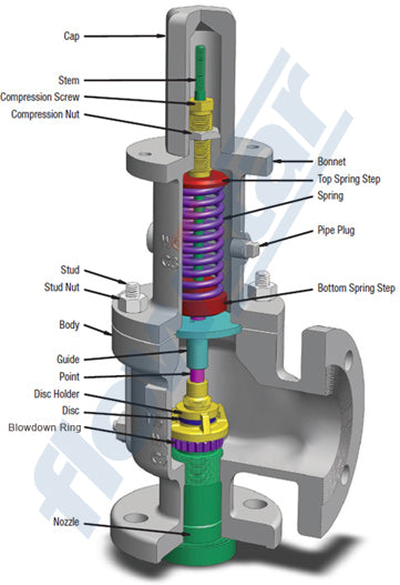
The basic elements of the design are right angle pattern valve body, inlet can be either a full nozzle or a semi-nozzle type. With a full nozzle design has the “wetted” inlet tract formed from one piece (as per figure 6) with the seat integrated into the top of the nozzle. The internal bore of the nozzle and the disc is the only part of the valve that is exposed to the process fluid with the valve in the closed position. A semi-nozzle design consists of a seating ring fitted into the body.The disc is held onto the seat by the stem, with the downward force coming from the compression on the spring mounted in the bonnet. The amount of compression on the spring is adjusted by the spring adjuster under the cap.


Unless bellows or diaphragm sealing is used, process fluid will enter
the spring housing (or bonnet). The amount of fluid depends on the
particular design of safety valve. If emission of this fluid into the
atmosphere is acceptable, the spring housing may be vented to the
atmosphere - an open bonnet. This is usually advantageous when the
safety valve is used on high temperature fluids or for boiler
applications as, otherwise, high temperatures can relax the spring,
altering the set pressure of the valve. However, using an open bonnet
exposes the valve spring and internals to environmental conditions,
which can lead to damage and corrosion of the spring.
When the fluid
must be completely contained by the safety valve (and the discharge
system), it is necessary to use a closed bonnet, which is not vented to
the atmosphere. This type of spring enclosure is almost universally used
for small screwed valves and, it is becoming increasingly common on
many valve ranges since, particularly on steam, discharge of the fluid
could be hazardous to personnel.

A lifting mechanism is recommended to test for correct valve
operation at all times where corrosion, caking, or any deposit could
prevent the opening operation.
Foreign particles can lodge under the
seat of the valve when it discharges. The lifting lever allows you to
lift the valve and flush the obstruction. Pressure relief valves for
Section VIII require a lift lever on all air, steam, and hot water
valves used at temperatures over 60 degC. Typically used where periodic
testing of the valve in location is desired to assure its operation.
With an Open lifting lever design, when the valve discharges, fluid
media will escape into the atmosphere around the open lifting lever
assembly. If this is not desirable or when back pressure is present you
would select a Packed Lifting Lever design.

As described above, this type is selected where leakage of the media to the atmosphere during valve discharge or during back pressure would be un-desirable. A packed lever design is a completely sealed assembly.

Some people consider a bolted and gasketed design better to the standard screw cap for applications with back pressure and / or vibration hence some manufacturers offer this as an option.

Under certain circumstances i.e. under the start-up conditions of a plant or to pressure test the system in a controlled environment, it may be required that the valve is prevented from opening.This is achieved by screwing the bolt (shown on the wire) into the cap which screws down onto the stem and prevents it lifting. Obviously it is important that test gags are removed prior to placing the valve into service.

The bellows is designed to cover the same area on the back of the disc equal to the seat area hence the back pressure will have no effect on the set pressure. See the previous section “Basic Safety Valve Principles”. Bellows also protects the spindle, spindle guide and spring from the process medium.

A micro switch is fitted on the exterior of the valve which is activated when the stem rises in the valve.
A bolt on steam jacket for preserving the valve body temperature. Typically used on fluids to prevent solidification of the flowing viscous fluids.
A disc is held against the nozzle by a spring, which is contained in a cast bonnet. The spring is adjusted by a compression screw to permit the calibration of opening or set pressure. An adjustable nozzle ring, threaded onto the nozzle, controls the geometry of the fluid exit control chamber (also known as a huddling chamber). The control chamber (huddling chamber) geometry is very important in controlling valve opening and closing pressures and stability of operation. The nozzle ring is locked into position by a ring pin assembly as shown in Figure 15 below.


Manufacturers usually state their recommended testing procedure and testing intervals in their Installation, Operating and Maintenance Instructions (IOM). Typically, they recommend a manual test every 3 or 6 months (assuming it has a lifting lever) and a set pressure test every 12 months. It is sensible to incorporate these into your maintenance plan so they are not missed. Sometimes your insurance company may require them to be tested even more regularly than this i.e. every 6 months. Testing in most cases involves removing them from your system and having them recertified in an approved workshop.
Safety valves and Relief valves are extremely reliable. The most common issues we come across however are:
(a) A valve passing (leaking) on the outlet side when the valve is supposed to be closed. This can happen to valves of any age (new or old) and occurs if debris contained in the medium passes through the valve at a point when the valve lifts, and the debris either traps or damages the internals of the valve. On soft seated valves, hard particles may embed themselves in the soft material causing re-sealing issues. If your valve has a lifting lever and it is safe to do so, then it is worth lifting the handle for a few seconds which will hopefully clear any debris allowing the valve to reseal correctly. If this isn’t an option or it doesn’t cure the problem, then the valve will need to be removed and returned for maintenance and recertification. The time we often see this the most is during the startup of a system and there is a pressure spike, hence this is why it is extremely important that a system is flushed out well before hand.
(b) Corrosion / wear which is usually only a problem on older valves or those in extremely harsh environments.
تعمیرات اساسی
ما خدمات جامع و کامل برای آزمایش، تست و تعمیر شیرها ارائه
می دهیم
خدمات ما شامل
* تهیه انواع قطعات یدکی شیرالات اطمینان
* بازرسی بصری برای خوردگی و آسیب تمام سطوح خارجی
و داخلی، در صورت لزوم ما NDT را برای اطمینان از اینکه هیچ نشتی وجود ندارد
* آزمایش فشار برای تعیین اینکه آیا دیسک و نازل صحیح عمل
میکند
* بازسازی قطعات داخلی برای اطمینان از عملکرد
صحیح
* جایگزینی قطعات آسیب دیده یا مشکوک از جمله دیسک
ونازل
* لپینگ برای بازگشت حالت اولیه (بدون هیچگونه نشتی(
* دوباره بازبینی طراحی شیریا تغییر نقطه تنظیم شیر
اطمبنان و طراحی شیرهای جدید
* رنگ شیراطمینان
* تست مجدد، کالیبراسیون، مجددا خدمات
* ارائه گواهی های قابل پیگیری (پلاک)
* ارائه مستندات کامل